Booster Hand: A Tendon-Driven, Underactuated Robotic Finger
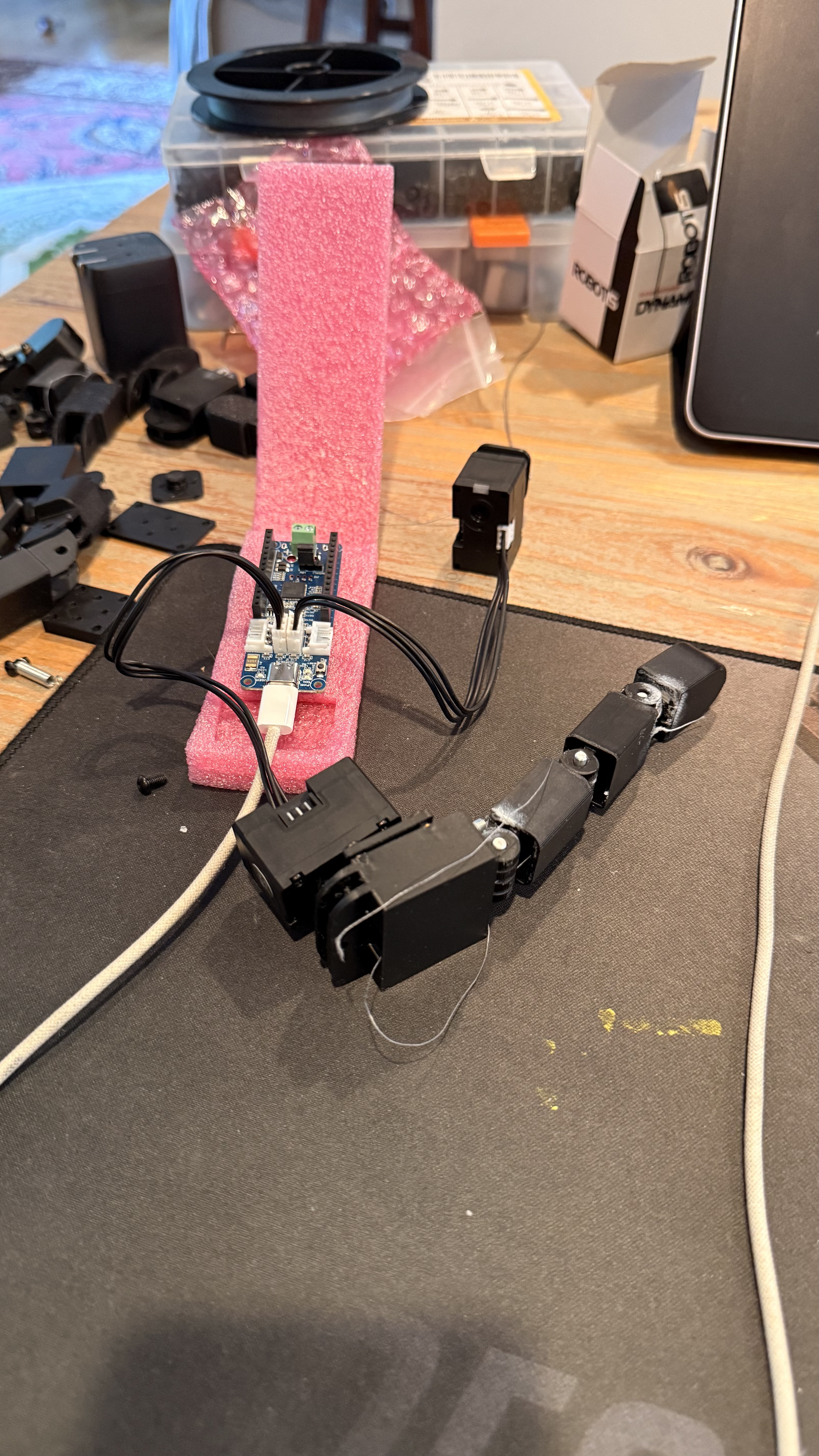
Status: 🚧 In progress. This page documents an active build — the finger described below is currently on a workbench, not in a display case. Sections marked open are problems I haven't solved yet. I'm posting it in this state on purpose: the debugging process is most of the engineering value here.
Overview
The Booster Hand is a 5-finger, tendon-driven robotic hand I'm designing for SIGRobotics' humanoid platform, with a fall 2026 deadline. The hand is being designed from scratch in Onshape (migrated over from SolidWorks), with three of us working on it: my brother Yusef Primus, our friend Manu Eldath, and me.
Human hands get away with 20+ degrees of freedom using only a fraction of that many motors, because tendons let one actuator drive several joints in a coordinated, mechanically-enforced sequence — the muscle in your forearm doesn't know it's flexing three joints in your finger, it just pulls a cable, and the finger's own geometry decides how that motion gets distributed. That's the effect I'm after here: underactuation — fewer motors than degrees of freedom, with the missing constraints supplied by mechanical coupling instead of extra electronics.
Rather than design all five fingers and the palm at once, I made a deliberate call to get one finger fully working first — actuation, coupling, and control all validated on a single, testable unit — before committing that design to four more fingers and a palm. Everything on this page is that single-finger prototype.
Design Philosophy: One Motor, Three Joints
The mechanism, in plain terms
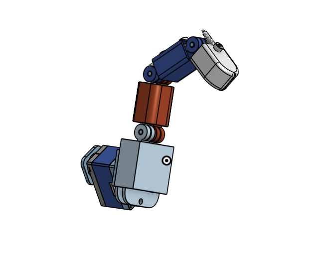
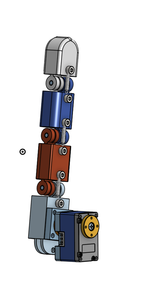
Picture the finger as four rigid links connected by three hinge joints:
- Link 0 — a grounded bracket that doesn't flex; it only swings side-to-side (abduction/adduction).
- Link 1 — the proximal phalanx, connected to link 0 at joint 1.
- Link 2 — the middle phalanx, connected to link 1 at joint 2.
- Link 3 — the distal phalanx (fingertip), connected to link 2 at joint 3.

Only joint 1 is directly actuated. A single tendon runs from a motor-mounted capstan (a grooved spool) to a capstan on link 1, and pulling it flexes joint 1. Joints 2 and 3 have no motor of their own — instead, two passive coupling tendons connect each joint to the one before it, so that as joint 1 flexes, joints 2 and then 3 flex automatically, in sequence, in a fixed, repeatable trajectory. A separate motor, mounted at the base, direct-drives link 0's side-to-side abduction independently of all of this.
That's the whole mechanism: one motor drives flexion, one motor drives abduction, and two passive tendons distribute the flexion motor's pull across three joints. The hard part — and the part that took several failed iterations to get right — is getting the passive tendons to actually transmit motion instead of just going slack.
Why this is harder than "just tie a string to it"
The first version of the coupling tendon was anchored entirely within the two links spanning the joint it was supposed to drive — e.g., tied between link 1 and link 2 to make joint 2 respond to joint 1. It produced zero tension, and joint 2 never moved. The reason is a little counterintuitive until you draw it out: if both ends of a cord are anchored to links that rotate together as a rigid pair around the joint being sensed, the cord has no way to detect that rotation at all — both anchors move in lockstep, so the distance between them never changes.
The fix is that the reference end has to anchor on the link before the joint you're trying to sense, not on the two links spanning it. For coupling tendon 1 (which drives joint 2 from joint 1's motion), that means anchoring the reference end on link 0, routing it through link 1, and terminating the driven end on link 2. Link 0 doesn't rotate through joint 1 at all, so as joint 1 flexes, the geometric path from link 0's anchor point, through the guide on link 1, genuinely changes length — and that change in length is exactly what gets transmitted to joint 2.
There's a second, similarly counterintuitive wrinkle: the reference segment has to be routed along the dorsal (back) side of the finger, not the palmar (front) side. The palmar surface is the one that compresses as the finger curls — a tendon there goes slack during flexion, which is the opposite of what a reference tendon needs to do. The dorsal surface stretches during flexion, so that's where a tendon builds tension. The driven segment (the part that actually pulls the next joint closed) stays on the palmar side, same as the main flexion tendon, because that's the side that needs to shorten to close the joint.
The Math
1. The coupling equation: how joint 1's rotation becomes joint 2's rotation
Variables:
- $\theta_1$ — rotation angle of joint 1 (the actuated joint), measured from the finger's straight/extended position.
- $\theta_2$ — rotation angle of joint 2 (the first passively-coupled joint), same reference.
- $r_{1c}$ — radius of the coupling tendon's reference-side capstan, centered on joint 1's pivot axis. This is how far off-axis the reference anchor point sits.
- $r_{2c}$ — radius of the coupling tendon's driven-side capstan, centered on joint 2's pivot axis.
- $s$ — the total length of the coupling tendon, from its fixed reference anchor to its fixed driven anchor.
Intuition first: the coupling tendon is one continuous piece of inextensible cord. If a length $\Delta s$ of it gets "used up" wrapping around the reference-side capstan as joint 1 rotates, that same length $\Delta s$ has to come from somewhere — and the only place it can come from is unwinding off the driven-side capstan at joint 2, which rotates joint 2 in the process. The two capstan radii set the exchange rate between the two joints' angles, exactly like two gears of different radii set an exchange rate between two rotation speeds.
Derivation:
For a cord wrapped around a capstan of radius $r$, the arc length consumed or released as the capstan rotates through an angle $\theta$ (in radians) is the standard arc-length relation:
As joint 1 flexes by $\theta_1$, the reference segment of the coupling tendon — anchored on link 0, wrapping at radius $r_{1c}$ around joint 1's axis — changes length by:
Because the tendon is inextensible, the total length $s$ is fixed. Any length gained on the reference side must be lost on the driven side, and vice versa:
The driven segment wraps a capstan of radius $r_{2c}$ at joint 2, so the length it releases corresponds to joint 2 rotating by $\theta_2$:
Setting the two equal and solving for $\theta_2$:
This is the governing relationship for the whole coupling scheme, and it repeats one joint up for coupling tendon 2 (joint 2 driving joint 3), with the analogous radii for that pair.
What this buys you, and what it costs: the ratio $r_{1c}/r_{2c}$ is a design knob — pick the two radii and you fix exactly how much joint 2 closes for a given amount of joint 1 closure, independent of load. That's the appeal of a coupled, capstan-driven scheme over a fully-passive, spring-and-friction "self-adaptive" underactuated finger: the trajectory is fixed and repeatable rather than depending on contact forces. The trade-off is exactly that: it gives up the self-adaptive grasping behavior (where a passive finger automatically conforms to whatever it touches) in exchange for predictability.
2. Motor-to-joint transmission ratio
Variables:
- $\theta_{\text{motor}}$ — rotation commanded at the flexion motor's output horn.
- $\theta_{\text{joint1}}$ — desired rotation at joint 1.
- $r_{\text{motor}}$ — radius of the capstan mounted on the motor horn.
- $r_{\text{link1}}$ — radius of the capstan on link 1, at joint 1, that the actuator tendon terminates on.
By the same arc-length-conservation logic as above (the actuator tendon is a single inextensible cord running from the motor capstan to the joint 1 capstan):
With the current geometry — $r_{\text{link1}} = 5\text{ mm}$, $r_{\text{motor}} = 4\text{ mm}$ (reduced down from an initial 5 mm target once the motor horn's bolt-circle geometry ruled that out), and a target of $\theta_{\text{joint1}} = 90°$ for full flexion:
That's comfortably inside a single motor revolution, which matters because the abduction motor runs in Extended Position Control Mode (more on that below) to handle signed angles through zero — but the flexion motor doesn't need that complexity, since 112.5° of travel never approaches the 0°/360° wraparound boundary that Extended mode exists to solve.
3. Tendon tension and force budget
Variables:
- $\tau$ — torque delivered at the motor's output shaft.
- $r$ — capstan radius at that shaft.
- $F$ — tangential tendon tension produced at the capstan surface.
For an idealized capstan (no friction losses, pure tangential pull), torque and tension relate the same way force and a lever arm always do:
The XL330-M288-T is rated for 0.52 N·m stall torque and roughly 0.10 N·m continuous (rated) torque at 5 V. At the current 4 mm capstan radius ($r = 0.004\text{ m}$):
That's the idealized force budget available to close the finger. In practice, this is an upper bound, not what actually shows up at the fingertip — every additional capstan the tendon wraps around introduces its own friction losses, and the observed behavior on the bench (a large initial pulling force needed before the finger "snaps" into flexion, with no controllable middle range) is consistent with friction and preload eating into that idealized number faster than the math alone predicts. That mismatch between the idealized force model and the observed behavior is one of the open problems below.
Electronics: Two Dynamixels on One Bus
Hardware
- Controller: OpenRB-150 — an open-source, Arduino-IDE-programmable board with the same pinout and form factor as an Arduino MKR, and four dedicated 3-pin TTL DYNAMIXEL ports built in for daisy-chaining Dynamixel actuators.
- Actuators: 2× Dynamixel XL330-M288-T servos (288.4:1 gear ratio, 20×34×26 mm, 18 g each).
- Cabling: Robot Cable-X3P (HRS), used to daisy-chain both motors onto the OpenRB-150's single DYNAMIXEL bus.
How the wiring actually works
Dynamixel's TTL protocol is a shared, half-duplex, multi-drop bus — both motors are wired onto the same 3-pin signal line (rather than each getting its own dedicated pair of wires back to the controller), daisy-chained motor-to-motor with the short Robot Cable-X3P jumpers, with the chain terminating at one of the OpenRB-150's DYNAMIXEL ports. What tells the controller which motor it's talking to isn't a separate wire — it's a unique ID number stored in each motor's onboard EEPROM. Every command packet sent down the shared bus includes a target ID, and only the motor with a matching ID responds.
Out of the box, Dynamixel motors often ship with the same default ID, which is a problem the moment you put two of them on the same bus — they'd both try to respond to every command. The abduction motor was permanently reassigned to ID 2 via its EEPROM (a one-time write, persists across power cycles) specifically to resolve that collision and let the firmware address each motor unambiguously.
Firmware: two control modes for two different jobs
The flexion motor and the abduction motor are commanded differently, because they need to do different things:
- Flexion motor — standard Position Control Mode. Its full range of motion (112.5°, per the transmission math above) never crosses the 0°/360° boundary, so ordinary position control is sufficient.
- Abduction motor — Extended Position Control Mode. Abduction needs signed angles roughly in the range −30° to +30° around a straight-ahead neutral position. Standard Position Control Mode on a Dynamixel doesn't handle "signed" motion the way you'd want — commanding a negative-equivalent angle causes it to travel the long way around the 0°–360° circle to get there, rather than taking the short path through zero.
OP_EXTENDED_POSITIONmode was adopted specifically to allow genuine signed position commands that pass cleanly through zero instead of wrapping the long way around.
One firmware bug worth documenting because of how it presented: a position-wait loop (the code that blocks until a motor has physically reached its commanded position before moving on) was reversing prematurely at roughly 87.9° instead of completing the intended 112.5° sweep. The cause was a leftover hardcoded threshold value from an earlier version of the code that no longer matched the actual target range — a good reminder to grep for magic numbers whenever a motion range changes.

Design Iteration Log
This project has moved forward almost entirely through print-test-measure-repeat cycles on a Bambu Lab A1 Mini (PLA). A few of the iterations that mattered most:
| Iteration | Problem found | Resolution |
|---|---|---|
| Pin hole tolerance | Needed a rotating fit for a 3.175 mm dowel pin | Swept 3.20–3.70 mm in 0.05 mm steps on a printed test coupon; 3.50 mm confirmed as a snug, freely-rotating fit (3.30 mm was too tight) |
| Heat-set insert hole tolerance | Cold hand-press "bind" test gave a false positive at 4.70 mm | Re-tested with actual heat (pull-out + twist test after cooling); 4.50 mm confirmed as correct heat-set sizing for the 4.5 mm OD M3 insert |
| Spring anchor screw spacing | Screw couldn't fully seat at 11 mm spacing — spring's relaxed length exceeded the gap, cocking its last coil and blocking the screw head | Widened to 13 mm, confirmed the screw now seats fully |
| Middle phalanx / spring interference | Sharp corner on the middle phalanx contacted the return spring at full flexion | 5 mm fillet applied — partial improvement only; root cause (fillet clearance and spring-anchor hole position are geometrically coupled through the same edge distance) still open |
| Coupling tendon 1, first attempt | Anchored entirely between the two links spanning the joint — zero tension, joint 2 never moved | Re-anchored the reference end on link 0 (the link before the sensed joint) instead of link 1 |
| Coupling tendon 1, second attempt | Reference segment routed on the palmar (front) side went slack during flexion instead of tightening | Rerouted the reference segment to the dorsal (back) side, which stretches during flexion |
| Capstan groove sizing | First-cut groove (4 mm wide × 1 mm deep) was roughly 30× oversized for the 0.14 mm braided tendon | Target reduced to ~0.2–0.3 mm width, ~0.15–0.25 mm depth (not yet physically validated against the printer's 0.4 mm nozzle) |
| Actuator capstan radius | Original 5 mm target physically overlapped the motor horn's bolt-circle holes | Reduced to 4 mm — see transmission-ratio math above for the resulting 112.5° motor sweep |
A few dead ends are worth naming explicitly, since re-deriving why something didn't work is more expensive than just remembering it didn't:
- Anchoring a coupling tendon at or near a joint's own pivot axis — even on the correct link, a point sitting at the center of rotation stays the same distance from every point on the rotating body no matter the angle, so it produces zero tension. The anchor needs a meaningful radial offset from the axis.
- Cold hand-press fit as a proxy for heat-set insert sizing — the "bind" felt at 4.70 mm turned out to be a printed-surface artifact (ooze / first-layer texture), not real engagement with the insert's knurling. Only a heated pull-out-and-twist test after cooling actually validates a heat-set fit.
- Sizing a revolve-cut axis off an unrelated reference face in Onshape (instead of the cylindrical face's own implicit centerline) silently produced a revolve that didn't overlap the solid at all — a cut that removed no material, with no error thrown.

CAD Models
Everything is modeled in Onshape. The finger assembly currently consists of:
- Link 0 — the grounded abduction bracket, temporarily bolted rigid to the abduction motor's horn via a two-piece square mounting plate (bolt pattern imported directly from the motor manufacturer's STEP file) for bench testing, ahead of a proper palm/case ground.
- Link 1 / Link 2 / Link 3 — the proximal, middle, and distal phalanges, each carrying one or two capstans depending on how many tendons route through it.
- Capstans — a reusable revolved-cut feature (sketch profile on a plane through the true cylinder axis, ~315° revolve leaving a solid land for structural attachment), copy-pasted and re-pointed across every joint that needs one.
- Stacked capstan pin joints — where two capstans share a single pin at one joint, they're offset along the pin's axial length (one with a press-fit bore, one with the standard rotating-fit bore) rather than placed side-by-side, since radial space at the joint is too tight for the latter.


Current Status & Open Problems
This finger is not finished. Two mechanical problems are actively being debugged:
- Coupling tendon slack/geometry issue. With the actuated tendon holding link 1 in flexion, links 2 and 3 are still loose enough to be pushed back with minimal force — meaning the coupling tendon isn't under tension in that pose. Two candidate causes are being tested: installation slack (a reserve length of cord that has to be taken up before the constraint engages), or non-monotonic reference-segment geometry (if the guide point on link 1 sits far enough from joint 1's pivot, the chord distance can rise and then flatten or reverse near full flexion — going slack exactly where it should be tightest). The diagnostic in progress: release the actuated tendon, flex joint 1 by hand through its full range, and feel whether the coupling tendon firms up and stays firm, or firms up mid-range and then softens again.
- Overall jerkiness. The finger requires a large initial pulling force before snapping into full flexion, with no controllable middle range. Leading suspects: oversized (unvalidated) capstan grooves letting the cord shift, PLA-on-PLA static friction at unlubricated pin joints, a return-spring preload stiffer than necessary, and friction losses compounding across several capstans in series.
What's next
- Bench-test coupling tendon 2 (link 1 → link 3, mirroring the now-confirmed topology of coupling tendon 1)
- Resolve the coupling tendon slack root cause via the hand-flex diagnostic above
- Physically validate capstan groove sizing against the printer's real resolution
- Confirm the stacked-flange arrangement at the joint 3 pin is anchored correctly
- Once the single finger is fully validated: palm design and the remaining four fingers
Team & Acknowledgments
Built with Yusef Primus and Manu Eldath as part of SIGRobotics' humanoid platform. The direct-drive abduction joint architecture is modeled on Kim & Park, "Gripper with Thumb Adduction/Abduction Joint for Enhanced In-hand Orientation Manipulation," IEEE Humanoids 2018.